


Transformer Solutions for Energy Storage and Battery Integration
Do not copy-paste a solar or wind transformer spec for a battery storage plant. The duty cycles are completely different.
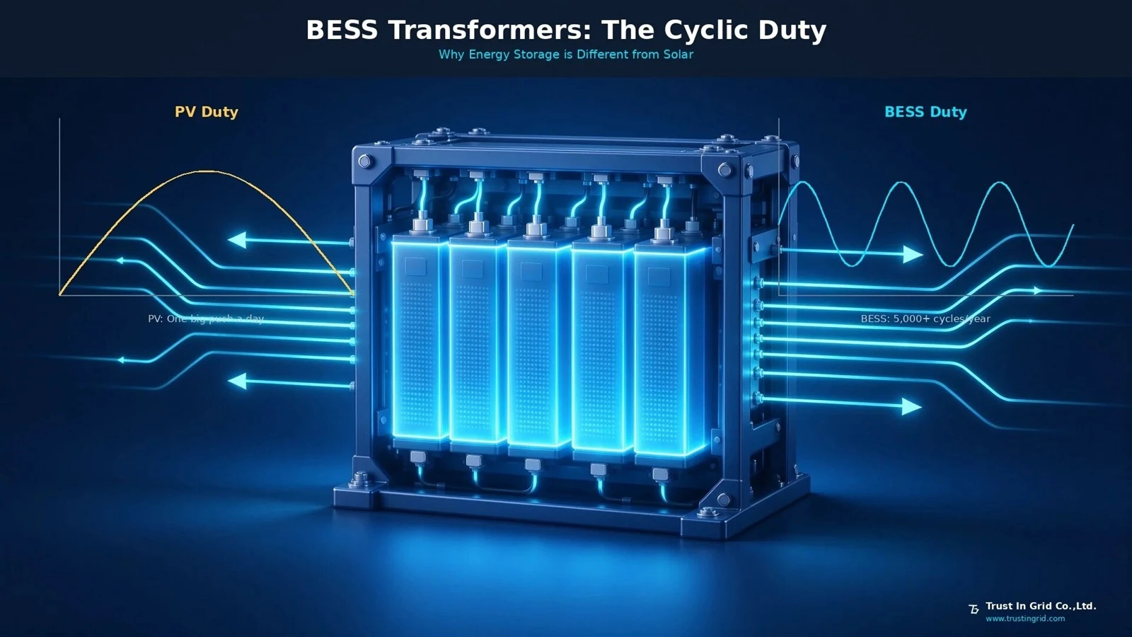
A PV transformer sees one big push a day and sits idle at night. A battery system? If it's doing frequency regulation, it cycles dozens of times a day. If it's peak shaving, it's two charges and two discharges. The current direction flips constantly. The windings and core are taking a beating from cyclic thermal stress.
Then there's the harmonic trap. Power conversion systems (PCS) use IGBT switching, so the AC output isn't a pure sine wave. Standard transformers are designed around sine wave loads. Hook them to a PCS, and those harmonic currents generate extra eddy losses in the windings and core.
Temperature climbs, insulation life plummets. If you don't map out the PCS harmonic spectrum during the sizing phase, the transformer either runs permanently derated or dies an early death.
Here is what storage transformers actually face in the field, and which parameters you cannot blindly copy from a standard distribution transformer.
1. Why You Can't Reuse a PV Transformer
Look at the load curve. A PV step-up transformer is high during the day, zero at night. A battery transformer's curve depends entirely on the business model. Frequency regulation means dozens of cycles a day. Co-located renewables follow the sun or wind. Every charge-discharge cycle means a power direction flip and a temperature swing. The copper and insulation paper expand and contract, and mechanical stress accumulates. Industry specs generally call for BESS transformers to handle 5,000+ cycles per year. A standard distribution transformer was never built for this.
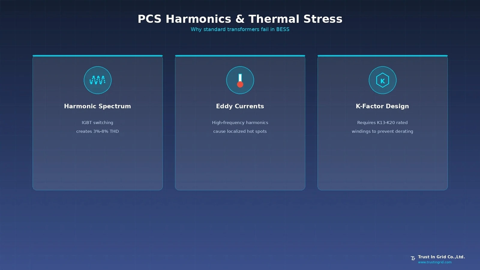
Now look at harmonics. Modern PCS units typically run at 3% to 5% Total Harmonic Distortion (THD) at rated power-mostly 5th, 7th, 11th, and 13th harmonics. Cost-optimized PCS can hit 6% to 8%. Those harmonics don't do useful work; they just turn into heat. For a 20MVA unit running at 8% THD, standard calculations might force you to derate to 17MVA-or just bite the bullet and buy a K-factor transformer.
2. Spec Comparison: Standard vs. BESS Transformer
| Parameter | Standard Distribution Transformer | Energy Storage Transformer (BESS) |
|---|---|---|
| Power Flow | Mostly unidirectional | Bidirectional, multiple flips per day |
| Cyclic Load | No specific requirement | 5,000+ cycles/year |
| K-Factor (Harmonic Tolerance) | Standard design | K13–K20 common |
| THD Tolerance | Low, assumes sine wave | 3%–8%, calculate based on PCS spectrum |
| Winding Design | Optimized for forward current | Reverse current and hot spot migration checked |
| Temp Design Margin | Standard limits | Recommend oil ≤45K, winding ≤50K |
| Cooling | ONAN/ANAF | ONAN/KNAN/ONAF/KNAF |
| Standard | IEC 60076 | IEC 60076 + IEEE C57.159 (Storage specific) |
IEEE C57.159 is the dedicated standard for energy storage transformers, explicitly covering cyclic bidirectional loading and design requirements under PCS harmonics. Citing this standard carries a lot more weight than a generic distribution spec.
3. Harmonics and K-Factor: No Room for Negotiation
PCS harmonics hit the transformer where it hurts. The 5th and 7th harmonics generate eddy current losses in the windings. Higher frequencies mean a bigger share of eddy losses. Standard transformer conductors are sized and transposed for power frequency. Under high-frequency harmonics, AC resistance climbs and localized hot spots become a real risk.
The K-factor quantifies a transformer's ability to handle non-linear loads. K13 means it can run a load with that specific harmonic profile without overheating. The required K-factor depends on the PCS THD and spectrum. If the PCS vendor provides measured data, tailor the winding design precisely. If you only have the nameplate THD, start at K13. For heavy harmonic loads, go straight to K20.
Another easily missed detail is electrostatic shielding. IGBT switching in the PCS generates high-frequency common-mode noise, which couples through the inter-winding capacitance to the HV side. Adding a grounded copper foil shield between the HV and LV windings filters this high-frequency interference. For a storage plant packed with communication and control systems, this affects more than just the transformer-it affects the whole system's stability.
4. Winding and Temp Rise Under Bidirectional Flow
A storage transformer cycles multiple times a day, and the winding temperature rides that load curve. Traditional temp rise design assumes steady-state load. Under cyclic duty, the thermal aging of insulation paper is not linear.
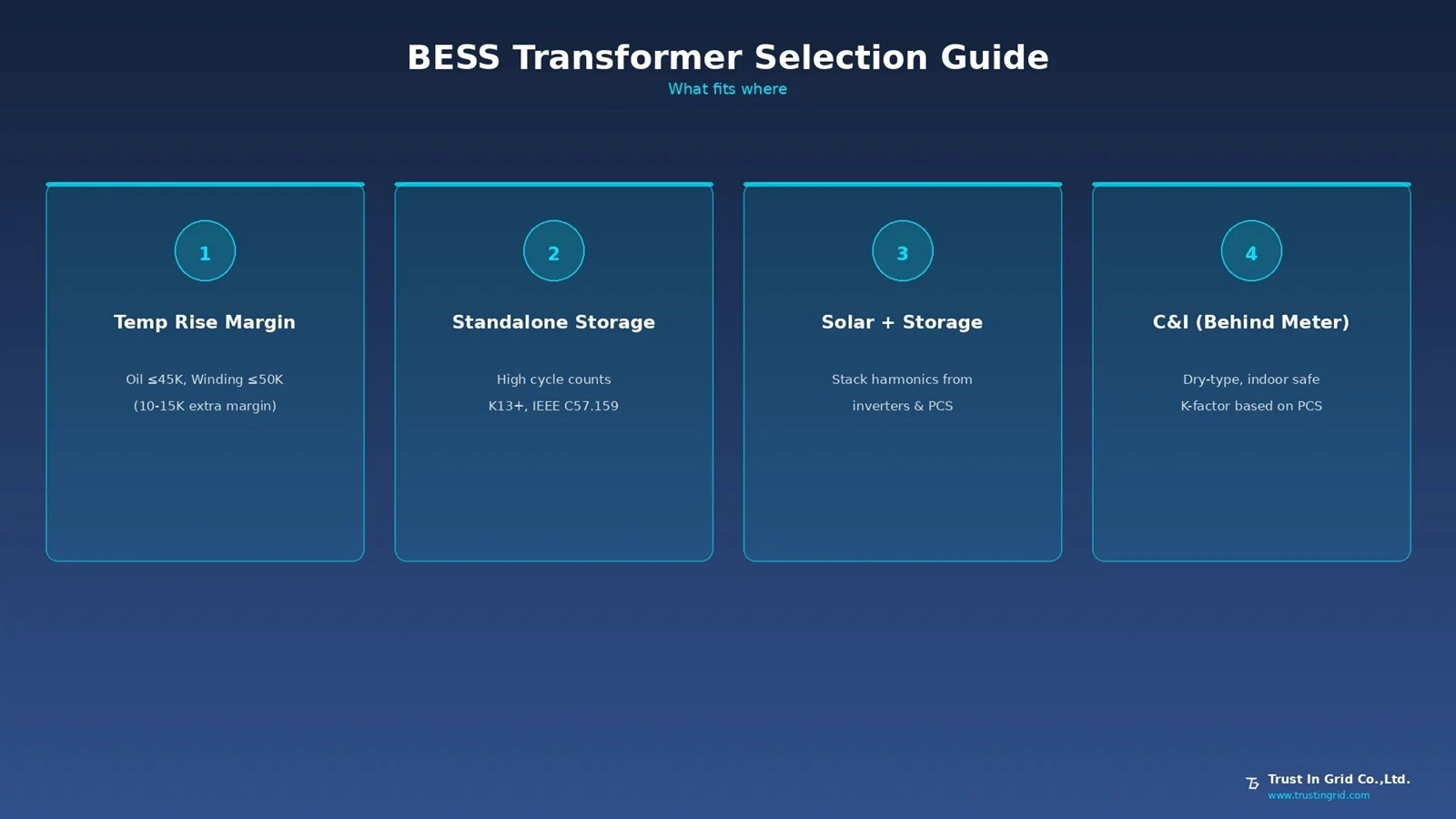
Practical engineering advice: squeeze the temp rise limits. Keep the oil temp rise under 45K and the winding temp rise under 50K. That gives you 10 to 15K more margin than the standard 60K/65K design. Yes, the transformer gets bigger and more expensive, but you buy back insulation life under cyclic duty. Replacing a transformer at a storage plant costs way more than the initial purchase premium.
Also, if multiple PCS units are tied to one transformer, look at split-winding designs. GB/T 51048-2025 (Design Standard for Electrochemical Energy Storage Stations) explicitly states that when multiple PCS units are paralleled and there's a need for harmonic and circulating current suppression, a split-winding transformer can be used. The split winding decouples the current paths of different PCS units on the magnetic circuit, reducing circulating currents and limiting the short-circuit impact if one PCS fails.
5. What Fits Where
Large standalone storage (frequency regulation, peak shaving): High cycle counts, frequent bidirectional flow. K13 or higher, temp rise margin built in, specified to IEEE C57.159. If you have the PCS harmonic data, custom-design the windings to the measured spectrum.
Renewable + storage hybrids: The storage and generation share the point of interconnection. The transformer might handle generation and charging at the same time. Confirm overload capacity when generation is at max and the battery is charging. Harmonic sources include both PV inverters and PCS-you have to stack them in the calculation.
Commercial and industrial storage (behind the meter): Small capacity, usually dry-type. Watch fire safety and footprint. K-factor based on the PCS harmonics. If it's going indoors or in a container, dry-type is the only way; oil is a non-starter.
Short-duration, high-power storage (supercaps, flywheels): High power density, short duration. The transformer design is closer to pulsed load. Talk to the manufacturer directly about thermal design and winding mechanical strength.
We build transformers and supply core materials. If you are evaluating transformer specs for a battery storage project-K-factor, cyclic rating, bidirectional winding design, or core grade-send us the details. PCS harmonic spectrum, cycle profile, capacity, voltage level, timeline. You will get a straight answer.
TIG - Trust in Grid
www.trustingrid.com
asia@trustingrid.com
References
[1] Power Conversion System PCS: BESS Architecture & Transformer Guide, Ruistelectric, 2026.
[2] NEMA US 80018-2022, Transformers in DC Applications: Design, Specification, Considerations and Recommendations, NEMA.
[3] GB/T 51048-2025, Design Standard for Electrochemical Energy Storage Stations, Section 8.2 Electrical Equipment Selection.
[4] Energy Storage (BESS) Transformer Solutions, GE Transformer, 2026.
[5] Energy Storage PCS Rectifier Transformer Matching Rules, Henan Tailong Power Equipment, 2026.